Product
Datasheet

DRV256
256 W USB Servo Driver with USB CDC, UART, Modbus RTU, and CANopen Bridging
✈ Drone ◯ Mobile Robot 🦾 Robot Arm System
Key Features
  • USB CDC virtual serial bridge for the actuator serial interface
  • Also supports UART, RS485, and CAN as alternate host interfaces ??same data as the USB CDC virtual COM port
  • Host packets are forwarded to all four servo ports without protocol translation
  • Four servo ports with power delivery, plus four ESC ports and one 4-channel ESC port
  • ESC outputs use the protocol selected by the ESC Protocol Type register: PWM, DSHOT300, or DSHOT600
  • Provides closed-loop velocity (speed) control for ESC outputs, in addition to direct throttle control
  • Dual 16 V / 8 A servo power domains, each feeding two servo ports, for 256 W total available servo power
  • Power may enter from USB-C charger input, 24 V header, or ESC-side 5 V supply
  • Two onboard status LEDs: LED1 turns on at bus voltage >= 11 V, and LED2 turns on when the PC USB device is configured
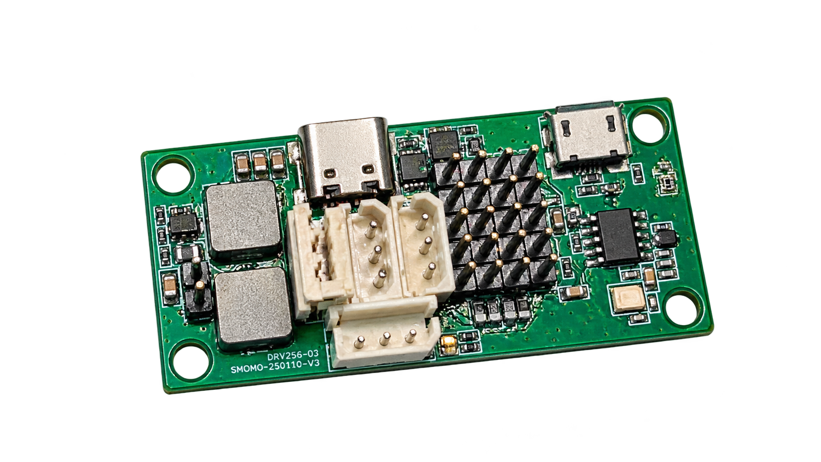
Product Image
DRV256 servo control board, background removed
Interface
USB Data Input
USB Micro / SM04B
1GNDGround
2D-USB data negative
3D+USB data positive
4VBUS+5 V
Host-facing USB CDC interface. Same connector family style as the camera products.
USB-C Charge Input
USB-C / SM04B
1GNDGround
2CC1Conf channel
3CC2Conf channel
4VCCPower only
Power-only USB-C path. No USB data lines are used on this connector.
24 V Header
1VINUp to 24 V
2GNDReturn
Primary high-power input for full 256 W servo-power operation, up to 12 A.
Host Serial Interfaces ??UART / RS485 / CAN
CAN, 4-pin 2.54 mm
1GNDGround
25V+5 V
3CANHCAN bus high
4CANLCAN bus low
UART / RS485, 4-pin 2.54 mm
1RXUART receive
2TXUART transmit
3ARS485 differential A
4BRS485 differential B
CAN bus rate is fixed at 1 Mbps. UART and RS485 are fixed at 115200 bps. Data sent and received over these interfaces is identical to what is sent and received when the USB CDC virtual COM port is open.
Motion Output Ports
Molex 5045 (3-pin)
1SIGSignal (serial)
2VCCServo power
3GNDGround
1x3, 2.54 mm
1GNDGround
2VCCESC power
3SIGSignal (PWM / DSHOT300 / DSHOT600)
Servo: 4 x Molex-compatible servo ports
ESC: 4 x 1x3 2.54 mm headers or 1 x SM06B 4-channel ESC port
The 4-channel ESC port and the four single ESC ports are mutually exclusive.
Because the servos are serial (daisy-chain) devices, more than one servo can be connected to a single port ??the number of servos per port is limited only by the board's available power budget, not by port count. ACT48's 48 W rating is a peak figure; since attached motors are rarely all moving at once, actual average power draw stays well under 48 W per servo, so more servos than a naive peak-power sum would suggest can typically be run.
Brief Specification
  • USB Device ClassUSB CDC virtual COM port 쨌 driver-free 쨌 baud rate ignored
  • Alternate Host InterfacesUART 쨌 RS485 쨌 CAN
  • UART / RS485 RateFixed 115200 bps
  • CAN Bus RateFixed 1 Mbps
  • Servo Ports4 ports, Molex-compatible actuator connector
  • ESC Ports4 x 1x3 2.54 mm + 1 x SM06B 4ch ESC
  • Power InputUSB Micro, USB-C charge-only, 24 V / 12 A header, ESC 5 V
  • Servo Power2 rails x 16 V / 8 A, each shared by 2 servos
  • ESC ControlPWM / DSHOT300 / DSHOT600 selected per ESC
  • Servo ID Range0-250 when ESC IDs are reserved
  • ESC IDs251, 252, 253, 254
  • ESC Model Number0xFF
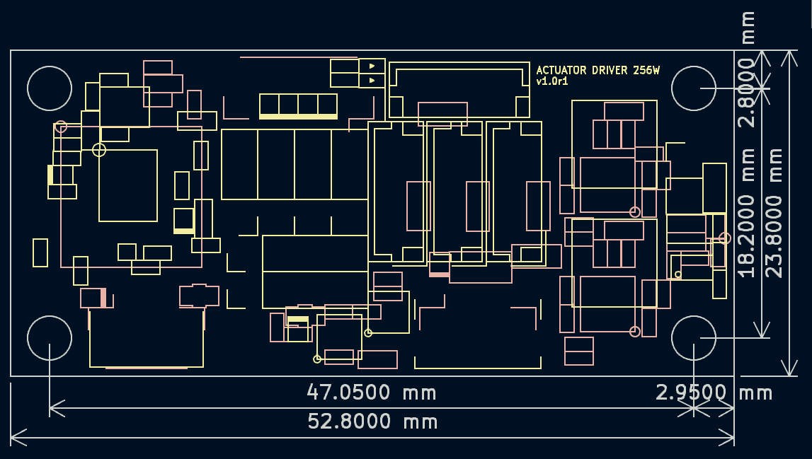
  • Dimensions65.6 x 23.8 x 3.5 mm
Dimensions
DRV256 dimensions
[ drv256_dim.png ]

Specification

DRV256
Electrical And Interface Reference - Rev 1.0
Parameter Condition / Group Value Unit / Note
USB And Power Inputs
USB Device TypeHost-facing portUSB CDCVirtual serial port
USB Data ConnectorMain host linkUSB Micro / SM04B-GHS-TBTCamera-compatible pinout
USB-C ConnectorPower onlyCharge-only inputNo data path
USB-C Sideband PinsPower-only connectorGND, CC1, CC2, VCCPin order
Header Input RatingMain power header24 / 12V / A max
ESC Auxiliary InputBackfeed allowed5V from ESC side
Alternate Host Interfaces
UART4-pin 2.54 mm headerFixed 115200 bpsSame payload as USB CDC
RS485Shares UART header (A/B)Fixed 115200 bpsSame payload as USB CDC
CAN4-pin 2.54 mm headerFixed 1 MbpsSame payload as USB CDC
Servo Power Delivery
Servo Power DomainsBoard internal2 railsIndependent supply groups
Per-Rail Servo PowerOne rail16 V / 8 A128 W
Ports Per RailServo outputs2Each rail feeds two servo ports
Total Servo PowerAll rails combined256W
ESC Power DeliveryESC outputsNot suppliedESCs are expected to power themselves
Motion Outputs
Servo Output CountActuator ports4Molex-compatible
ESC Output CountSingle ESC ports41x3, 2.54 mm headers, ESC10645 compatible
4ch ESC Output *Shared ESC group1SM06B, ESC40630 compatible
ESC Output ProtocolGenerated by bridgePWM / DSHOT300 / DSHOT600Selected per ESC by register 0x83
Mechanical
Dimensions (L x W x H)Board only65.6 x 23.8 x 3.5mm
Power Routing Summary
USB data enters through the USB Micro / SM04B path. Power may enter from the USB-C charge input, the 24 V / 12 A header, or an ESC-provided 5 V rail. Servo power is actively distributed by the board, but ESC outputs are signal-only because ESC modules are assumed to source their own power.
ⓘ * Mutual Exclusion: The 4-channel ESC output and the four single ESC ports share the same ESC routing group and must not be used at the same time.

Control And Mapping

DRV256
USB CDC Bridge, Servo Broadcast, And ESC Register Support
ⓘ DRV256 is a USB CDC virtual COM port device. No baud rate setting is needed ??the transport is USB virtual serial, so the host baud rate is a placeholder only (any value works in practice).
1. USB CDC Bridge Behavior ??Host baud setting is a placeholder; transport is USB virtual serial.

Packet Path: Host virtual COM port -> USB CDC device -> board bridge -> all four servo ports in parallel.
Servo-originated packets from individual downstream devices are merged by the board and sent back upstream through the same USB CDC channel.
The bridge does not reinterpret servo packets. For standard servos it forwards the original serial frame as-is. For ESC targets it converts the command intent to the protocol selected by the ESC protocol register (`0x83`).
All servos connected to a single DRV256 must be set to the same baud rate on the servo-side serial bus. DRV256 automatically detects the connected servos' baud rate ??no manual baud rate configuration is required on the board. Only these servo-side baud rates are supported: 115200, 1 Mbps, 2 Mbps.
In addition to USB CDC, DRV256 exposes UART, RS485, and CAN as alternate host interfaces (see Interface, Page 1). Whichever interface is used, the data sent and received is identical to what is sent and received when the USB CDC virtual COM port is open ??only the physical transport differs.

The serial packet format forwarded by DRV256 follows the same protocol used by the servos themselves.
See Actuator Serial Interface.
drv256_dashboard.html is a self-contained, zero-install browser application (Web Serial API) for DRV256 development and testing. No driver installation is needed on any OS, and host baud-rate setting is irrelevant ??the transport is USB virtual serial.
After connecting, add one or more motor IDs (0??54) to track: the dashboard automatically treats IDs 251??54 as ESC targets and all other IDs as standard servos, reading back each tracked motor's Position, Velocity, Current, Torque, Voltage, and Temperature as live line-graph subplots. A built-in packet builder lets you pick a command (READ / WRITE / ADD / COMMIT / ABORT and their *_WITH_ACK variants), target ID list, and register address/value, and assembles the resulting frame in a raw hex editor with byte-by-byte syntax highlighting, live validation, CRC auto-fix, and one-click send ??plus a System/RX log of all traffic.
See DRV256 Dashboard.
2. ID And Model Number Allocation
Device Class Model Number ID Range Description
Standard servo *Product-specific0-250Available range when the USB Servo Driver reserves the upper IDs for ESC outputs.
ESC channel 10xFF251Mapped to ESC output 1
ESC channel 20xFF252Mapped to ESC output 2
ESC channel 30xFF253Mapped to ESC output 3
ESC channel 40xFF254Mapped to ESC output 4
* Using DRV256 reduces ACT48's usable ID range to 0-250.
ESC Control Table

DRV256
Nonvolatile And Volatile ESC Register Subset
3. ESC Control Table
ESC endpoints on DRV256 do not follow the actuator serial document's full servo control table. For ESC IDs 251 through 254, use the ESC-specific control table below. The bridge accepts the same packet format on USB CDC and selects PWM, DSHOT300, or DSHOT600 from register 0x83. Register 0xD1 controls the corresponding ESC LED through AM32 DShot commands 22..29; the command is sent only after the ESC has received stop frames. Register 0xC9 changes the ESC's persistent direction setting using DSHOT commands 7/8 followed by save command 12. A negative throttle temporarily reverses direction only on DSHOT endpoints, using command 20 or 21 without modifying 0xC9; PWM input is always unidirectional and clamps negative commands to its minimum pulse. bDShot extended telemetry is enabled only after eight stop frames and the command-13 repeat sequence has completed. If an ESC that had supplied extended telemetry stops replying for 4 s, the bridge latches the telemetry-stale error and disarms that endpoint. The two DRV256 board LEDs are independent of ESC register 0xD1: LED1 indicates bus voltage >= 11 V, and LED2 indicates that the PC USB device is configured.
3-1. Nonvolatile Area ??persistent across power cycles
Addr Type Name Access Default Description
0x80u8Model NumberR0xFFAlways reads as 0xFF.
0x81u8Firmware VersionRVariesESC firmware revision exposed through the bridge.
0x82u8IDR251-254Fixed to 251, 252, 253, or 254 depending on ESC channel.
0x83u8Protocol TypeR/W10 = PWM, 1 = DSHOT300, 2 = DSHOT600.
0x84u8Return Delay TimeR/W250Return delay in 2 us units before the bridge returns an ESC read or ACK response.
0x85u8Operating ModeR/W00x00 = Throttle, 0x01 = Current, 0x02 = Velocity. Position and Extended Position modes are not available for ESC endpoints.
0x8Eu8Temperature LimitR/W80When telemetry reaches this threshold, the bridge reduces the output throttle ceiling by 1% per second until temperature falls below the limit.
0x8Fu16Max Voltage LimitR/W16000Upper supply limit; crossing it latches the hardware-error flag but does not derate output.
0x91u16Min Voltage LimitR/W5000Lower supply limit; low voltage derates output by 1% per second and disarms after 100 seconds continuously below the limit.
0x93u16Current LimitR/W3000When valid bDShot current telemetry reaches this value, output throttle is reduced by 1% per second and the hardware-error flag is latched.
0x95i16Max Velocity LimitR/W32767Non-negative maximum RPM magnitude. When exceeded, the bridge reduces the output throttle ceiling by 1% per second until RPM falls below this limit. The default is INT16_MAX; 0 is a valid limit and permits only zero measured RPM. Negative values are invalid and latch the hardware-error flag.
0xB1u16PWM MinR/W1000Minimum PWM pulse width in microseconds when the ESC protocol is 0 (PWM).
0xB3u16PWM MaxR/W2000Maximum PWM pulse width in microseconds when the ESC protocol is 0 (PWM).
0xB5u16PWM TimeoutR/W10000If raw throttle input has no new command for this many microseconds, the PWM output falls to PWM Min; 0 disables the timeout. PWM input is always unidirectional.
0xBDu16Velocity P GainR/W0Closed-loop velocity proportional gain; gain scale is 1/1024.
0xBFu16Velocity I GainR/W0Closed-loop velocity integral gain; gain scale is 1/1024.
0xC1u16Velocity D GainR/W0Closed-loop velocity derivative gain; gain scale is 1/1024.
0xC3u16Current P GainR/W0Current-to-throttle proportional gain; gain scale is 1/1024.
0xC5u16Current I GainR/W0Current-to-throttle integral gain; gain scale is 1/1024.
0xC7u16Current D GainR/W0Current-to-throttle derivative gain; gain scale is 1/1024.
0xC9u8Reverse DirectionR/W00 = normal spin direction; 1 = reversed spin direction. On DSHOT endpoints the bridge applies this through the ESC's persistent direction setting and save command. A negative raw/current/velocity command temporarily reverses relative to this setting without changing it. PWM endpoints ignore direction and remain unidirectional.
0xCAu16Current Anti-Windup ShiftR/W3Integral decay shift at current-PID saturation. Smaller values unwind faster; valid effective range is 1-15.
0xCCu16Velocity Anti-Windup ShiftR/W3Integral decay shift at velocity-PID saturation. Smaller values unwind faster; valid effective range is 1-15.

ESC Control Table

DRV256
Volatile ESC Register Subset
3-2. Volatile Area ??resets to initial value on power-up

ESC endpoints reject unsupported addresses normally; in particular 0x97-0x9C and 0xE6-0xE7 are not part of the ESC register map.

Addr Type Name Access Initial Description
0xD0u8Torque EnableR/W0Mapped to ESC arming state.
0xD1u8ESC LEDR/W0Supported on ESC IDs 251..254. The bridge maps these IDs to AM32 DShot LED0..LED3 and sends commands 22..25 for ON or 26..29 for OFF. The command is deferred until the ESC is stopped.
0xD4u8Hardware Error StatusR0Latched error mask: bit 0 = overcurrent, bit 1 = overtemperature, bit 2 = voltage limit, bit 3 = unsupported PWM operating mode, bit 4 = bridge queue/transport overrun, bit 5 = stale bDShot telemetry, bit 6 = invalid ESC/PWM configuration. Bits remain set until reboot.
0xD5u8MovingR0xFFValid only while bidirectional DSHOT telemetry is available. 0xFF means unsupported or unavailable.
0xD6i16Goal CurrentR/W0Signed target current in mA. It is used only in Operating Mode 1; other ESC modes ignore this register. On DSHOT, a negative target requests the temporary reverse direction.
0xD8i16Goal VelocityR/W0For ESC endpoints this is a speed target in RPM, not the 0.1 deg/s unit used by standard servos. It is used only in Operating Mode 2; a negative target requests temporary reverse on DSHOT.
0xE8u16Present CurrentR-1ESC input current in mA. Standard EDT type 0x06 remains whole amperes. ESCLITE sends type 0x08 first: bits 0..6 carry the 0.01 A remainder and bit 7 carries the extra 0.125 V voltage step. The driver caches that extension, commits current when the following 0x06 arrives, and commits voltage when the following 0x04 arrives. This gives 10 mA current resolution while a generic FC may continue to read 0x06 as whole amperes and ignore 0x08 as device-specific debug. The u16 driver register saturates at 65535 mA.
0xEAi16Present ThrottleR0Present throttle command, in 4096-step units. For ESC endpoints this reflects drive strength, not the power-based torque measurement used by standard servos.
0xECi16Present VelocityR-1Present shaft velocity in RPM. Requires valid bidirectional DSHOT telemetry; -1 means unsupported or unavailable.
0xF6u16Present Input VoltageR-1Present supply voltage from extended bidirectional DSHOT telemetry, in mV. Standard EDT type 0x04 remains 0.25 V/LSB; ESCLITE sends its type 0x04 after the 0x08 extension and adds 0.125 V when bit 7 of that cached field is set. The DRV256 therefore exposes 125 mV resolution. Update rate is determined by the ESC firmware's extended telemetry scheduler. -1 means unsupported or unavailable.
0xF8u8Present TemperatureR-1ESC temperature from extended bidirectional DSHOT telemetry, in degrees C. -1 means unsupported or unavailable.
0xF9i16Raw Throttle / Present PWMR/W0Raw throttle command in Operating Mode 0. On PWM endpoints it is always unidirectional: 0 maps to PWM Min, positive values linearly map to PWM Max, and negative values clamp to PWM Min. A nonzero operating mode forces minimum output and latches the unsupported-mode error.

Fieldbus Bridge

DRV256
Modbus RTU and CANopen over the native actuator serial core
Host Interface Rules
  • USB CDC and host UART keep the original actuator serial protocol unchanged.
  • RS485 is a Modbus RTU slave interface at 115200 bps, 8N1.
  • CAN is a Classical CAN 2.0A interface at 1 Mbit/s with a compact CANopen CiA 402 subset.
  • Both fieldbus interfaces translate host requests into actuator serial packets internally.
  • The bridge emits translated serial packets only on servo ports where the target servo ID was found during scan.
  • Duplicate servo IDs are allowed on the native serial path (USB CDC / host UART), but are not allowed on RS485 Modbus RTU or CANopen. Fieldbus access is rejected if one servo ID is found on multiple servo ports.
  • Servo-side firmware remains serial-only. No Modbus RTU or CANopen parser runs inside the servo.
Protocol Scope
BusImplemented Host View
USB CDCNative actuator serial packets, unchanged
UARTNative actuator serial packets, unchanged
RS485Modbus RTU slave with motion-oriented holding registers
CANCANopen with SDO access to CiA 402 style control objects and basic RPDO/TPDO exchange
Translation Path
Host Modbus RTU or CANopen request
↓
DRV256 firmware fieldbus parser
↓
Internal serial packet builder
↓
Port-selective single-wire servo packet transmission
RS485 / Modbus RTU Map
Default slave address = servo_id + 1. Supported function codes: 03h, 06h, 10h.
Register Type Meaning Access Internal Serial Mapping
0x0000u16ControlwordR/W0xD0 Torque Enable. Standard CiA 402 values 0x0006, 0x0007, 0x000F are accepted; only 0x000F asserts torque.
0x0001u16StatuswordRBridge shadow: 0x0040 switch-on disabled, 0x0021 ready to switch on, 0x0023 switched on, 0x0027 operation enabled.
0x0002u16Operating ModeR/W0x85 control mask. CANopen values 10 torque, 3 velocity, and 1 position translate to native masks 1, 2, and 4.
0x0010i16Target TorqueR/W0xD6-0xD7
0x0011i16Target VelocityR/W0xD8-0xD9
0x0012-0x0015i64Target PositionR/W0xDA-0xE1
0x0020i16Present TorqueR0xEA-0xEB
0x0021i16Present VelocityR0xEC-0xED
0x0022-0x0025i64Present PositionR0xEE-0xF5
0x0026u16Bus VoltageR0xF6-0xF7
0x0027u8TemperatureR0xF8
0x0030u16Profile VelocityR/W0xE6-0xE7; standard-servo endpoints only, unsupported by ESC endpoints.
0x0031u16Current LimitR/W0x93-0x94
CAN / CANopen Object Subset
Node-ID = servo_id + 1. SDO and a compact PDO set are supported. Target objects are translated into actuator serial packets internally. RPDO1 carries 6040h and optionally 6060h; RPDO2 payload interpretation follows the currently selected mode.
Index Type Meaning Access Internal Serial Mapping
6040hu16ControlwordR/W0xD0 Torque Enable. 0x0006, 0x0007, 0x000F map to the compact CiA 402 state subset; only 0x000F enables torque.
6041hu16StatuswordRCompact CiA 402 shadow: 0x0040, 0x0021, 0x0023, 0x0027.
6060hi8Modes of OperationR/W0x85 Operating Mode Mask. Supported CANopen values: 10 torque → native 1, 3 velocity → 2, 1 position → 4.
6061hi8Modes DisplayRBridge shadow using the same 10/3/1 values.
6071hi16Target TorqueR/W0xD6-0xD7
60FFhi32Target VelocityR/W0xD8-0xD9, sign-extended
607Ahi32Target PositionR/W0xDA-0xE1, sign-extended from 32-bit host value
6077hi16Actual TorqueR0xEA-0xEB
606Chi32Actual VelocityR0xEC-0xED, sign-extended
6064hi32Actual PositionR0xEE-0xF5, truncated/clamped to 32-bit
6081hu32Profile VelocityR/W0xE6-0xE7; standard-servo endpoints only, unsupported by ESC endpoints.
1017hu16Producer Heartbeat TimeRBridge-local heartbeat timer

Pricing

DRV256
Standard Unit Pricing - Rev 1.0
Part Number Naming Rule
DRV USB Servo
Driver
256 Power
Rating (W)
-
x Country
Prefix
DRVUSB Servo Driver
Power Rating
256Maximum 256 W total servo power
Country of Origin
CChina
KKorea
XUnspecified
Sample Unit Pricing - DRV256 Series
Listed price is for a representative sample unit. Volume pricing available on request.
Part Number Description Qty Unit Price
DRV256-X 256 W USB Servo Driver, country unspecified 1 pcs US$ 50
ⓘ Volume pricing available for orders of 10 units or more - contact us for a quote. ✉ hyon646@gmail.com
How to Order

Select your model using the Part Number Naming Rule above and specify the Country of Origin option when placing an order.

Lead Time (stock) 1-3 business days
Lead Time (order) 4-6 weeks
Minimum Order Qty 1 pcs (standard) - 10 pcs (volume)
Payment PayPal - Bank Transfer - Other (on request)
Shipping Worldwide - DHL / FedEx / EMS
Contact hyon646@gmail.com
Document Revision History
Version Date Description
v1.0 2026-07-03 Initial Release