Product Datasheet
MIC0528 · 5CH MICARRAY
5-Channel MEMS Microphone Array with SSL
Key Features
- 5-channel MEMS microphone array with integrated SSL (Sound Source Localization) — 4 fixed peripheral microphones + 1 optional floating microphone (5th mic)
- Wide bandwidth support — 5-mic: SSL mode up to 96,000 Hz *, Highspeed mode up to 384,000 Hz (infrasound & ultrasound capable); 4-mic: SSL mode only, up to 96,000 Hz
- 8-LED ring instantly indicates detected sound direction — all 8 LEDs are directional, with 1 yellow LED marking the 0° reference; with 5-mic, LED brightness encodes signed elevation with upper/lower hemisphere; with 4-mic, operation is limited to a hemispherical region and LED brightness encodes |elevation| only
- USB 2.0 Highspeed (480 Mbps) — UAC 2.0 and CDC dual-class support
- Plug-and-play: compatible with Linux / Windows / macOS, no driver required (UAC)
- LED ring and operating settings configurable via CDC COM port — manual LED control, SSL output, barometric output, and SYNC signal enable/disable; settings persist across power cycles
- SYNC pin enables multi-microphone hardware synchronization; when SYNC is not in use, the pin operates as a GPIO
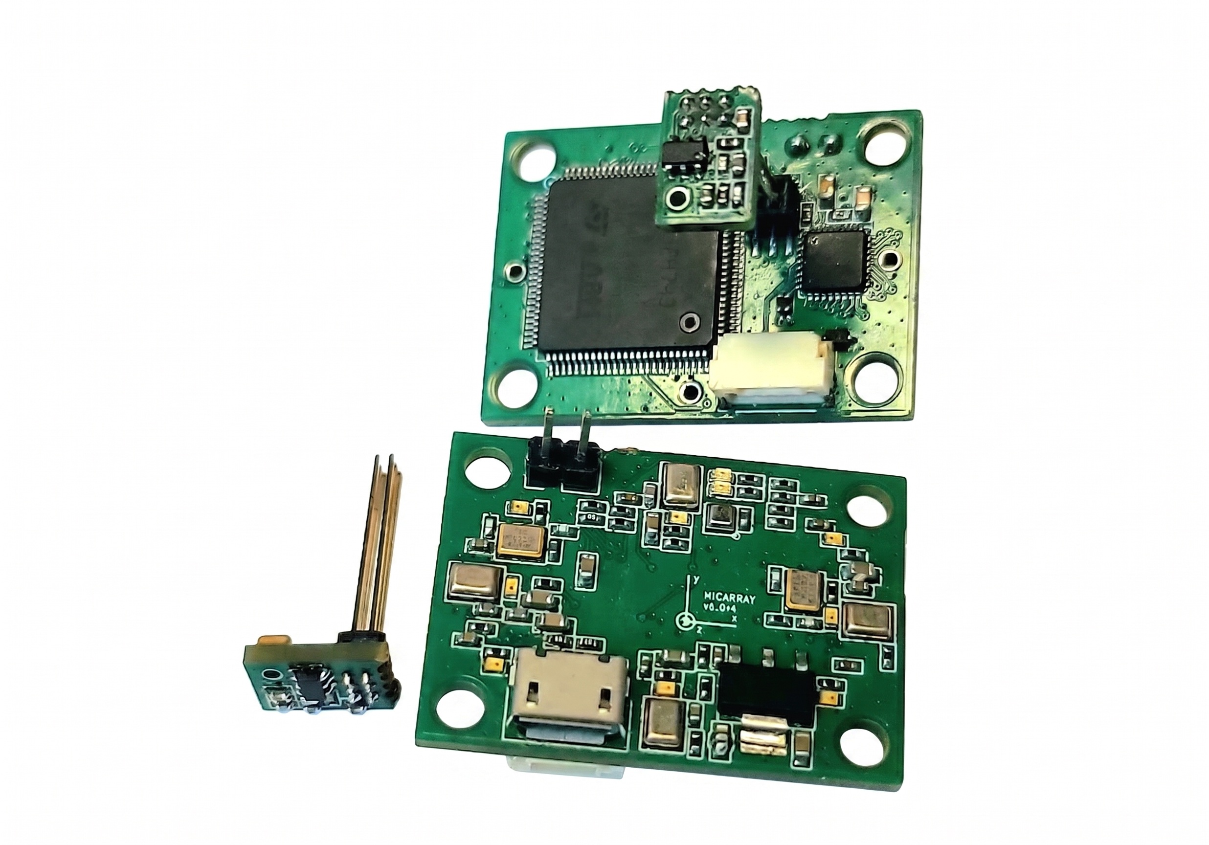
Product Image
Brief Specification
- Input Power 5 V / 230 mA (typ.) / 300 mA (max)
- Channels 1ch/2ch/5.1ch (SSL) · 1ch (Highspeed, 5-mic only)
- Sample Rate 24,000 – 384,000 Hz (5-mic) · 24,000 – 96,000 Hz (4-mic)
- Bit Depth 16-bit
- SSL Yes — spherical DOA (5-mic) / hemispherical DOA (4-mic; no upper/lower distinction)
- USB Class UAC 2.0 + CDC
- Interface USB 2.0 Highspeed
- Operating Temp. −20 °C ~ +70 °C
- Dimensions (L×W×H) * 32.8 × 23.8 × 3.5 mm
* Excluding microphone capsules.
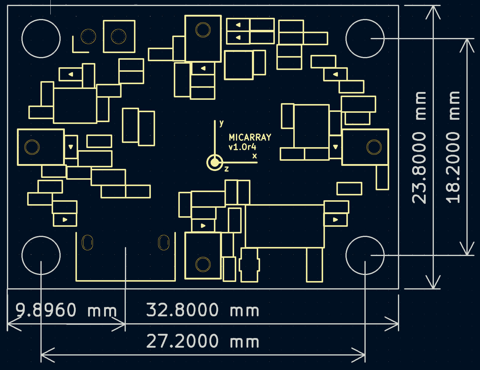
Dimensions
Full Specification
5-Channel MEMS Microphone Array with SSLFull Technical Reference · MIC0528 · 5CH MICARRAY Rev 1.0
| Parameter | Condition / Mode | Value | Unit |
|---|---|---|---|
| Audio | |||
| Microphone Configuration | 5-mic (MIC05285x) | 4 circular peripheral microphones + 1 floating microphone (optional, 5th mic) | — |
| Microphone Configuration | 4-mic (MIC05284x) | 4 circular peripheral microphones only — floating microphone not installed | — |
| Audio Capture | SSL mode (5-mic) | 5-mic · 96,000 Hz · 16-bit * | — |
| Audio Capture | SSL mode (4-mic) | 4-mic · 96,000 Hz · 16-bit | — |
| Audio Capture | Highspeed mode (5-mic) | 1-mic · 384,000 Hz · 16-bit | — |
| Sound Source Localization (SSL) | |||
| Angular Error (Azimuth) | Typical | 20 | ° |
| SSL Update Rate | — | 8 | Hz |
| SSL Frequency Range | Full | 100 – 9,900 | Hz |
| SSL Frequency Range | Practical | 600 – 4,000 | Hz |
| Output | 5-mic (floating installed) | Spherical DOA: azimuth + elevation — upper/lower hemisphere distinguished | — |
| Output | 4-mic (no floating mic) | Hemispherical-region DOA: azimuth + |elevation| only — upper/lower PCB-plane hemisphere not distinguished | — |
| Power Supply | |||
| Supply Voltage (VDD) | Rated input | 5.0 | V DC |
| Supply Voltage (VDD) | Absolute maximum | 9.0 | V DC |
| Current Consumption | Active | 230 (typ.) / 300 (max) | mA |
| Current Consumption | Standby | 20 | mA |
| Power Dissipation | T_amb = 25 °C | 1.5 (typ.) | W |
| USB Interface | |||
| USB Standard | — | USB 2.0 | — |
| Speed Mode | — | Highspeed | 480 Mbps |
| USB Class | — | UAC 2.0 (audio) + CDC (control) | — |
| UAC 2.0 Bit Depth | All modes | 16 | bit |
| UAC 2.0 Sample Rates — 1ch (5-mic) | 16-bit | 24,000 / 48,000 / 96,000 / 192,000 / 384,000 | Hz |
| UAC 2.0 Sample Rates — 1ch (4-mic) | 16-bit | 24,000 / 48,000 / 96,000 | Hz |
| UAC 2.0 Sample Rates — 2ch / 5.1ch | 16-bit | 24,000 / 48,000 / 96,000 * | Hz |
| Connector Type | — | USB Micro / SM04B-GHS-TBT | — |
| VBUS Input | — | 5.0 ± 0.25 | V |
| SYNC / GPIO Interface | |||
| Connector | — | 2.54 mm Pin Header, 2-pin | — |
| Pin Assignment | Pin 1 | SYNC / GPIO — Synchronization Signal or GPIO | — |
| Pin Assignment | Pin 2 | GND | — |
| SYNC Pulse Rate | SYNC mode | 2.9296875 | Hz |
| SYNC Pulse Width | SYNC mode | 1 audio sample LOW per period | — |
| SYNC Marker | 1ch / 2ch / 6ch · SYNC active | Last channel outputs INT_MIN for 1 sample at SYNC rising edge * | — |
| GPIO Update Rate | GPIO mode (max) | 100 | Hz |
| R/W Resolution | — | 1 | bit |
| SYNC / GPIO Exclusion | — | GPIO and SYNC are mutually exclusive — when GPIO is active, SYNC is disabled regardless of CDC f-command setting | — |
| LED Interface | |||
| LED Update Rate | SSL / SYNC mode | 7.5 | Hz |
| LED Count | Ring | 8 | — |
| LED Brightness Resolution | — | 3-bit (8 levels, 0 = off, 7 = full) | — |
| Manual Control | — | Via CDC COM port (l command) | — |
| Environmental & Reliability | |||
| Operating Temperature | Continuous | −20 ~ +70 | °C |
| Storage Temperature | Non-condensing | −40 ~ +85 | °C |
| Humidity (Operating) | Non-condensing | 10 ~ 90 | % RH |
| Mechanical | |||
| Dimensions (L × W × H) | PCB + housing, excl. capsules | 32.8 × 23.8 × 3.5 | mm |
| Weight | PCB + housing, excl. capsules | 3.7 ± 0.3 | g |
| Mounting | — | 4× M3 screw | — |
| Acoustic Characteristics | |||
| Sensitivity | 1 kHz, 94 dB SPL | −26 ± 1 | dBFS |
| SNR | A-weighted, 94 dB SPL | 65 | dB(A) |
| THD | 100 Hz–10 kHz, 94 dB | < 0.2 | % |
| THD | 100 Hz–10 kHz, <110 dB | < 1 | % |
| Acoustic Overload Point (AOP) | THD = 10% | 120 | dB SPL |
| Phase Deviation | 100 Hz–10 kHz | < 2 | ° |
* SSL mode: Inter-channel amplitude and phase coherence within the audible range (≤ 24,000 Hz) is guaranteed; coherence in the ultrasonic range (> 24,000 Hz) is not guaranteed.
Operating Modes Reference
5-Channel MEMS Microphone Array with SSLRecording Modes · USB Output Modes · MIC0528 · 5CH MICARRAY Rev 1.0
5-mic variant: in SSL mode, measurement results are delivered as a 6-channel stream with 5 SSL audio channels and 1 dedicated subwoofer channel; Highspeed 1-channel 384,000 Hz mode is also available. 4-mic variant: SSL mode only; its measurement results are also delivered as a 6-channel stream, with ch5 and ch6 unused. The 4-mic SSL output operates over a hemispherical region and reports azimuth + |elevation|, without upper/lower PCB-plane hemisphere distinction.
1-1. Recording Modes
| Mode | Channels | Sample Rate | Bit Depth | Variant | Note |
|---|---|---|---|---|---|
| SSL mode | 6ch | 96,000 Hz * | 16-bit | 5-mic / 4-mic | Full array · spherical DOA (5-mic) / hemispherical DOA (4-mic) via CDC; ch5–ch6 unused for 4-mic |
| Highspeed mode | 1ch | 384,000 Hz | 16-bit | 5-mic only | 1ch floating microphone · maximum bandwidth · SSL disabled |
* SSL mode: Inter-channel amplitude and phase coherence within the audible range (≤ 24,000 Hz) is guaranteed; coherence in the ultrasonic range (> 24,000 Hz) is not guaranteed.
1-2. USB Output Modes
When SYNC is active, the last channel outputs INT_MIN for 1 sample at each SYNC rising edge (2.9296875 Hz). The actual marker value may differ from INT_MIN depending on the host volume setting.
| Channels | Sample Rate (Hz) | Mode | Variant | Note |
|---|---|---|---|---|
| 1ch | 24,000 / 48,000 / 96,000 | SSL | Floating microphone (5-mic) / left peripheral microphone (4-mic) · standard bandwidth | |
| 192,000 / 384,000 | Highspeed | 5-mic only | Single floating microphone · maximum bandwidth · SSL disabled | |
| 2ch | 24,000 / 48,000 / 96,000 | SSL | High-frequency band: left & right peripheral microphones; low-frequency band: floating-microphone subwoofer signal added (5-mic) / left & right peripheral microphones (4-mic) | |
| 6ch | 24,000 / 48,000 / 96,000 | SSL | All 5 microphone elements (ch1–5) + 1 subwoofer (ch6) (5-mic) / all 4 microphone elements (ch1–4) + unused ch5 + ch6 (4-mic). The 6ch subwoofer channel (ch6) carries frequency components below 70 Hz; summing ch5 and ch6 provides a flat frequency response. |
* SSL mode: Inter-channel amplitude and phase coherence within the audible range (≤ 24,000 Hz) is guaranteed; coherence in the ultrasonic range (> 24,000 Hz) is not guaranteed.
Microphone Array Configuration
5-Channel MEMS Microphone Array with SSLElements · Frequency Range · MIC0528 · 5CH MICARRAY Rev 1.0
Board center is defined as (0, 0, 0). The coordinate axes are printed on the PCB. All values are in millimetres. Z = 0 is the PCB plane.
| Parameter | Value | Description |
|---|---|---|
| Element Count | 4 or 5 | 4 circular peripheral elements equally spaced at 90° + 1 floating element (5th microphone, optional) |
| Array Geometry | Circular | Peripheral elements arranged on a circle |
| Element Type | MEMS | Fusion of multiple MEMS units |
| Frequency Range | 0 * – 48,000 Hz | 5I · SSL mode |
| 0 * – >80,000 Hz ** | 5I · Highspeed mode | |
| 10 – 48,000 Hz | 5N · SSL mode | |
| 10 – >80,000 Hz ** | 5N · Highspeed mode | |
| 70 – 48,000 Hz | 4N · SSL mode |
* Constant reference point is the barometric pressure at recording start. Below 4 Hz, noise floor increases. ** Actual frequency response extends well above 80,000 Hz; guaranteed up to 80,000 Hz only. Array Design Note (5-mic variant): the 4 peripheral elements have intentionally reduced ultrasonic sensitivity to minimize broadband noise in standard audio recording; ultrasonic content is attenuated, not entirely absent. The floating element retains full ultrasonic sensitivity for dedicated high-frequency capture.
2-1. Individual Microphone Positions
| X (mm) | Y (mm) | Z (mm) | Description |
|---|---|---|---|
| −14.352 | 0.000 | 0.000 | Peripheral — −X axis |
| +14.352 | 0.000 | 0.000 | Peripheral — +X axis |
| 0.000 | −9.852 | 0.000 | Peripheral — −Y axis |
| 0.000 | +9.852 | 0.000 | Peripheral — +Y axis |
| −4.180 | −3.463 | −20.000 | Floating mic (5-mic only) |
SSL & LED Reference
5-Channel MEMS Microphone Array with SSLSound Source Localization · LED Ring · MIC0528 · 5CH MICARRAY Rev 1.0
8 ring LEDs (7 red + 1 yellow at 0° reference) visualize the SSL output in real time. When multiple sources are detected, multiple LEDs illuminate simultaneously. Elevation is encoded in LED brightness — lower elevation produces lower brightness. With the 5-mic variant, brightness encodes true signed elevation with upper/lower hemisphere; with the 4-mic variant, the device operates in a hemispherical region and brightness encodes |elevation| only. Each LED can be manually controlled (brightness 0–7) via the l command on the CDC COM port; brightness 8 restores firmware SSL output.
Ring LED Spec
| Parameter | Value | Note |
|---|---|---|
| Ring LED Count | 8 | Circular arrangement, one per 45° |
| Update Behavior | Real-time | Tracks SSL output continuously / User manual control via CDC COM port |
| LED Update Rate | 30 | Hz |
| LED Brightness Resolution | 3-bit | 8 levels (0 = off, 7 = full) |
* Ring LEDs are driven directly from the SSL engine output with no user configuration required.
Elevation Accuracy by Variant
| Variant | Behavior |
|---|---|
| 5-mic | The floating microphone enables full 3D spherical localization with hemisphere distinction. SSL accuracy is reduced in the lower hemisphere opposite from the floating mic. |
| 4-mic | Without the floating microphone, upper/lower hemisphere distinction is not possible. Output is azimuth + |elevation| only, and LED brightness reflects only |elevation| magnitude. |
On-board SSL Performance & Installation Note
| Item | Details |
|---|---|
| On-board SSL | The on-board SSL engine runs within the device MCU real-time budget, so algorithm complexity, angular error, multi-source separation, and noise robustness are constrained. The result is a practical estimate suitable for general use, not a high-precision measurement. |
| Host-side SSL | For higher-accuracy localization, users can capture raw multichannel audio and run their own SSL algorithm on the host. Multiple arrays can be hardware time-aligned via SYNC to further improve accuracy. |
| Installation | The sound propagation path between the source and the array must be free of obstacles. Brackets, enclosure walls, or nearby structures can attenuate or reflect sound and degrade SSL accuracy. |
Status LEDs
Green and blue status LEDs are positioned at the top of the device to indicate current power and streaming status. The ring LEDs are user-controllable via CDC COM port; brightness and pattern can be overridden independently of SSL output.
| Operating State | Blue LED | Green LED |
|---|---|---|
| Power On (USB Enumeration Complete) | ON | OFF |
| SSL Mode | ON | ON |
| Highspeed Mode (5-mic only) | OFF | ON |
Control & Data Interface
5-Channel MEMS Microphone Array with SSLCDC Output · Host Commands · MIC0528 · 5CH MICARRAY Rev 1.0
Real-time tracking data is provided via USB CDC as a virtual COM port. Since this is a virtual COM port, the baud rate setting is ignored and the host may set any baud rate. The port uses 8 data bits with parity (8N1 or as configured by the host). Up to 10 sources can be tracked simultaneously (3 sources are practical for standard operation). If multiple sound sources are detected in a single frame, the device transmits multiple lines sequentially.
SSL Result Format
| Parameter | Unit / Type | Description |
|---|---|---|
| id | Integer | Unique source identifier (tracks individual sound sources) |
| time | Milliseconds | Report timestamp (frame index × 0.1s) |
| phi / theta | Degree × 100 | Azimuth (phi) and Elevation (theta) in spherical coordinates, encoded as degree × 100 |
| center_hz | Hertz (Hz) | Estimated center frequency of detected source |
| activity | 0 – 1000 | Activity level (ASD), range 0–1000. Values ≥ 500 indicate active source. |
Status Format
Status output reports device runtime information via the CDC COM port when enabled. The temperature measurement point is the MCU internal temperature.
| Parameter | Unit / Type | Description |
|---|---|---|
| time | Milliseconds | Current time |
| usage% | 0 – 100 | CPU usage |
| temp | °C × 10 | MCU temperature in Celsius, encoded as temperature × 10 |
Barometric Measurement Format (I Option Only)
| Parameter | Unit / Type | Description |
|---|---|---|
| time | Milliseconds | Report timestamp |
| pressure | Pa | Barometric pressure value (%.4f) |
GPIO Measurement Format (GPIO Mode Only)
GPIO samples are transmitted on the 8 Hz CDC output cycle. When the GPIO update rate is set above 8 Hz (e.g. 100 Hz), multiple samples accumulate per cycle and are sent as a burst; at 100 Hz, up to approximately 13 samples may be batched in a single transmission.
| Field | Size / Type | Description |
|---|---|---|
| time | Milliseconds | Timestamp of the first sample in the batch |
| value | 1 byte × len | Values; each byte is '0' or '1' |
CDC Input Format (PC → Device)
| Command | Parameter | Description |
|---|---|---|
| p | 0 / 1 | SSL output via COM port — 0: disabled; 1: enabled |
| t | 0 / 1 | Status output via COM port — 0: disabled; 1: enabled |
| s | none | Save all current in-RAM settings to flash |
| r | none | Factory reset — restore all settings and save to flash |
| l | XY (X: 0–9, Y: 0–8) | LED manual control. X = LED index (0–9); Y = brightness (0–7 manual, 8 = restore firmware SSL/mode default) |
| b | 0 / 1 | Barometric output via COM port — 0: never; 1: output when barometer is present |
| f | 0 / 1 | SYNC signal output — 0: disabled; 1: enabled. No effect when GPIO mode is active (treated as f0). |
| gp | 0–100 | GPIO auto-sampling rate in Hz (0 = off). When nonzero, the device auto-samples at the specified Hz and transmits batches each 8 Hz CDC cycle; it also clocks out buffered gw data at that rate. When 0, voltage goes high on gw receipt; send g0 to read. |
| g | 0 / 1 | GPIO direction — 0: read (0/1); 1: write (0/1). When no auto-rate is set, sending g0 immediately returns one sample. |
| gw | len×1 bytes data; each byte is '0' or '1' | Push output data into the output buffer. Data is consumed at the rate set by gp; if no rate is set, the output is applied immediately and held until the next gw. |
| i | read: none / set: 0–255 number (e.g. i120) | Set/get mic ID. Send i to read the current ID, or send i0–i255 to set the identifier used in multi-microphone systems. |
Persistence: commands take effect immediately but are not written to flash until s is sent. On power-up, the last saved flash state is restored. r resets to factory defaults and saves automatically.
SYNC & GPIO Reference
5-Channel MEMS Microphone Array with SSLHardware Synchronization · GPIO Mode · MIC0528 · 5CH MICARRAY Rev 1.0
The SYNC pin normally carries the inter-microphone synchronization pulse. When SYNC synchronization is not required, the same pin can be reconfigured as a general-purpose GPIO. GPIO mode and SYNC mode are mutually exclusive: activating GPIO mode disables SYNC output regardless of the CDC f-command setting (treated as f0). Connecting multiple MIC0528 arrays via SYNC hardware-aligns all audio streams to a single time reference.
6-1. GPIO Reference
| Parameter | Value | Note |
|---|---|---|
| Maximum Update Rate | 100 Hz | Configurable via gp command (0–100) |
| R/W Resolution | 1-bit | |
| SYNC / GPIO Exclusion | Mutually exclusive | GPIO active → SYNC disabled |
6-2. SYNC Pin Assignment
Each MIC0528 provides a dedicated SYNC I/O pin header (2.54 mm, 2-pin). Connecting the SYNC pins between units allows one automatically designated device to generate a shared reference pulse distributed to all others. When active, the last channel of each recording stream outputs INT_MIN for 1 sample at each SYNC rising edge (5-mic: 1ch / 2ch / 6ch; 4-mic: 4-mic); full 16-bit audio resolution is maintained at all other times.
| Pin | Signal | Description |
|---|---|---|
| 1 | SYNC | Synchronization pulse (output on generator unit, input on all others) |
| 2 | GND | Ground reference — connect to common GND between units |
SYNC Signal Characteristics
| Parameter | Value | Note |
|---|---|---|
| Connector | 2.54 mm Pin Header, 2-pin | Standard pitch, vertical |
| SYNC Pulse Rate | 2.9296875 Hz | One reference pulse every ≈341.3 ms |
| SYNC Pulse Width | 1 audio sample LOW | Replaced by marker at SYNC point — interpolate adjacent samples to recover signal |
The 2.9296875 Hz SYNC marker (INT_MIN spike, 1 sample wide at each rising edge) provides a common reference point across all units, enabling manual frame alignment of multi-channel recordings in post-processing. The actual marker amplitude may differ from INT_MIN depending on the host volume setting.
6-3. Host-side SSL with Multi-Array SYNC
Connecting multiple MIC0528 arrays via SYNC hardware-aligns all audio streams to a single time reference. Host-side SSL can then treat all microphones across all units as one large-aperture array, increasing spatial diversity and localization accuracy. This approach is not limited by on-chip processing capacity; any algorithm can be applied on the host.
| Configuration | Role |
|---|---|
| 3 × MIC05284N-X + 1 × MIC05285I-X | 17 microphones total. The central MIC05285I-X provides 3D spherical SSL, infrasound sensing, and acts as the SYNC pulse generator; the three MIC05284N-X units expand spatial coverage with peripheral microphones. |
All four units are hardware-synchronized for host-side SSL across a 17-element aperture. MIC05284N-X units omit the floating microphone, keeping unit cost low while maximizing spatially distributed element count.
Dashboard
5-Channel MEMS Microphone Array with SSLFisheye Camera Option · Evaluation Tool · MIC0528 · 5CH MICARRAY Rev 1.0
A browser-based test dashboard is provided for MIC0528 operation with the CAM0412 and CAM0510 fisheye-lens camera options. The dashboard overlays the MIC0528 SSL direction on the fisheye camera view and provides Web Serial / Web Audio / WebRTC controls for evaluation and application prototyping.
| Item | Usage |
|---|---|
| Open Dashboard | mic0528_dashboard.html |
| Browser | Use Edge / Chromium-based browser with Web Serial and camera access. If local file access blocks device permissions, serve the folder through localhost or HTTPS and open the same mic0528_dashboard.html file. |
| MIC0528 Setup | Connect MIC0528 by USB, click COM Port Add to authorize the CDC port, select the port, then click Connect Mic. Use Start Recording to enable Web Audio capture and channel spectrogram display. |
| CAM0412 / CAM0510 | Select the fisheye camera device, click Connect Camera, then set center X/Y and 180° radius so the circular fisheye image aligns with the overlay grid. |
| SSL Overlay | When CDC SSL output is enabled, the dashboard draws the detected azimuth/elevation result on top of the fisheye image. For 5-mic operation the overlay represents spherical DOA; for 4-mic operation it represents hemispherical-region DOA and does not distinguish the upper/lower PCB-plane hemisphere. |
| Controls | The right control panel can enable/disable SSL, SYNC, barometric, CPU/temperature, GPIO, and LED settings through the CDC COM port. Manual LED values 0–7 override brightness; value 8 restores firmware SSL-driven LED behavior. Use Save s to store persistent device settings. |
| License | The dashboard is released into the Public Domain. Use the code from this dashboard to develop user applications. Copying, modifying, and reverse-engineering the dashboard HTML structure to create user applications is permitted without approval. |
Calibration & Warranty
5-Channel MEMS Microphone Array with SSLFactory Calibration · MIC0528 · 5CH MICARRAY Rev 1.0
All MIC0528 units are individually calibrated before shipment to ensure consistent performance across the microphone array. Calibration data is stored on-device and applied automatically during operation.
| Parameter | Details |
|---|---|
| Factory Calibration | All units calibrated before shipment for optimal performance |
| Calibration Warranty Period | 2 years from date of purchase |
| Post-Warranty Guarantee | Phase matching and SSL accuracy not guaranteed after warranty period expires |
| Recalibration Service | Available from manufacturer — contact hyon646@gmail.com for details |
For sustained SSL accuracy in long-term deployments, recalibration is recommended after the 2-year warranty period.
Part Number Naming Rule
Active Channels
- 4 4-mic — peripheral mics only
- 5 5-mic — incl. floating mic (default)
Infrasound
- I Support (default)
- N No support
Country of Origin
- C China
- K Korea
- X Unspecified
Sample Unit Pricing
5-Channel MEMS Microphone Array with SSLStandard Unit Pricing · MIC0528 · 5CH MICARRAY Rev 1.0
| Part Number | Active Ch | Infrasound | Qty | Unit Price |
|---|---|---|---|---|
| MIC05285I-X | 5-mic | Supported | 1 pcs | US$ 120 |
| ↳ MIC05285I-X | 5 pcs | US$ 100 | ||
| MIC05285N-X | 5-mic | No Support | 1 pcs | US$ 100 |
| MIC05284N-X * | 4-mic | No Support | 1 pcs | US$ 90 |
How to Order
| Lead Time (stock) | 1 – 3 business days |
| Lead Time (order) | 4 – 6 weeks |
| Minimum Order Qty | 1 pcs (standard) · 10 pcs (volume) |
| Payment | PayPal · Bank Transfer · Other (on request) |
| Shipping | Worldwide · DHL / FedEx / EMS |
| Contact | hyon646@gmail.com |
Document Revision History
| Version | Date | Description |
|---|---|---|
| v1.0 | 2026-04-19 | Initial Release |