Product Datasheet
SM3324 · MULTI-SENSOR TOOLKIT
Modular Multi-Sensor Toolkit
Key Features
- Modular multi-sensor platform (33 × 24 mm PCB) — options c / v / i / p / a / t combinable freely; ADC streaming up to 300 kSPS single-ch, 150 kSPS dual-ch, 37.5 kSPS 7-ch simultaneous; 2 Mbaud USB CDC, driver-free on Linux / Windows / macOS
- Option v — Non-contact AC voltage: capacitive coupling probe, ±1000 V range
- Option c — Clamp-type AC/DC current: ±50 A range with shielded transducer
- Option i — Attitude module: ICM-42670 IMU, LIS3MDL mag, BMP581 baro, VL53L4CX LiDAR; onboard EKF at 2400.96 Hz
- Option p — Dual phototransistor VIS (P cmd) + IR (Q cmd); up to 300 kSPS per channel or 150 kSPS simultaneous
- Option a — Two 12-bit ADC inputs 0–3.3 V; 300 kSPS single or 150 kSPS simultaneous
- Option t — Temp & humidity sensor: ±0.2 °C / ±2 %RH; ~18.76 Hz firmware update rate
- MQ-series gas sensor — PCB footprint provided for direct solder-mount; accessible via 'G' / 'g' commands
- Single ASCII-byte command interface — selects channel and sample rate; ADC and IMU modes on the same USB port
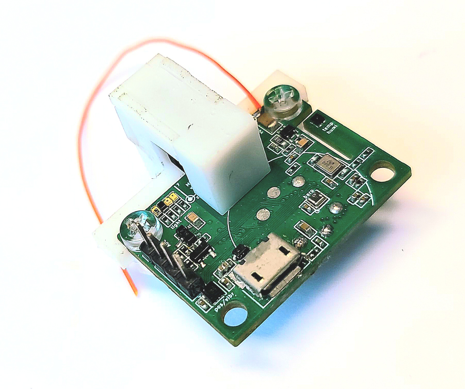
Product Image
Brief Specification
- MCU STM32F446RE · Cortex-M4 · 168 MHz
- USB Full-Speed 12 Mbps · CDC ACM · 2 Mbaud · driver-free
- ADC (onboard) 12-bit · 300 kSPS single / 150 kSPS dual / 37.5 kSPS ×7 ch
- Supply 4.75 – 5.25 V (USB bus) · 60 mA (typ) / 80 mA (max) all options active
- PCB 33 × 24 mm · 4 × M2 mounting holes
- Op. temp. −20 to +70 °C
- Option c — Current ±50 A · Hall-effect · DC – 23 kHz · AC/DC
- Option v — Voltage ±1000 V AC · capacitive · <10 Hz – >100 kHz
- Option i — Attitude 6-axis IMU ±2000 °/s ±16 g · Mag ±16 G · Baro 300–1250 hPa · LiDAR 1–6000 mm · EKF 2400.96 Hz
- Option p — Photo IR 940 nm + VIS · 0603 SMD · up to 300 kSPS each
- Option a — ADC ×2 0 – 3.3 V · 12-bit · up to 300 kSPS each
- Option t — Temp/RH ±0.2 °C / ±2 %RH (typ.) · −40 to +125 °C · 16-bit
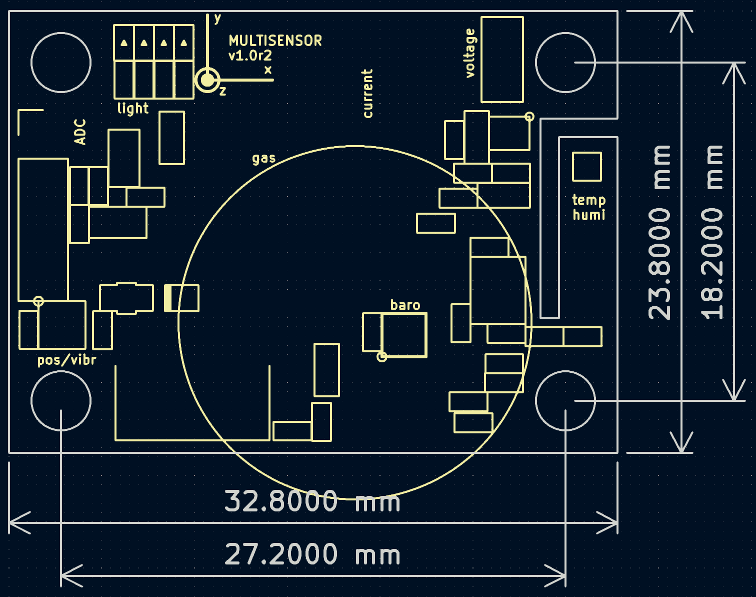
Dimensions
Full Specification
Modular Multi-Sensor ToolkitFull Technical Reference · SM3324 · MULTI-SENSOR TOOLKIT Rev 1.0
| Parameter | Condition / Mode | Value | Unit |
|---|---|---|---|
| General / Platform | |||
| Supply Voltage | USB bus | 4.75 – 5.25 V (USB bus) | — |
| Supply Current | — | 60 mA (typ) / 80 mA (max) | — |
| Dimensions | PCB | 33 × 24 ×24 mm | — |
| Mounting | — | 4 × M3 corner holes — use non-magnetic (plastic / nylon) fasteners to avoid interference with the onboard magnetometer | — |
| Operating Temp. | — | −20 to +70 | °C |
| Storage Temp. | — | −40 to +85 | °C |
| USB Data Interface Performance | |||
| USB Standard | — | USB 2.0 Full-Speed (12 Mbps physical) | — |
| USB Class | — | CDC ACM — virtual COM port | — |
| Connector | — | USB Micro-B | — |
| Effective Data Rate | Host streaming | 2 Mbaud | — |
| Host Buffer (recommended) | Recommended | ≥ 1 MiB receive buffer | — |
| Command Interface | — | Single ASCII char + LF (0x0A) | — |
| OS Support | — | Linux / Windows / macOS — driver-free | — |
| Frame Size | — | 32 bytes = 16 × u16 little-endian | — |
| Frame Counter | — | 16-bit, 1 bit embedded per word (LSB) | — |
| Max Forward Slip | USB drop tolerance | 8192 frames | — |
| Sampling | |||
| Single-ch. rate (high, uppercase) | High speed | 300 | kSPS |
| Single-ch. rate (low, lowercase) | Low speed | 18.75 | kSPS |
| Dual-ch. rate (high) | Interleaved | 150 kSPS each | — |
| Dual-ch. rate (low) | — | 9.375 kSPS each | — |
| 7-ch. rate (A command) | A command | 37.5 kSPS each | — |
| 7-ch. rate (a command) | a command | 2.34375 kSPS each | — |
| Option C — Current Measurement (Clamp Meter) | |||
| Measurement Range | — | ±50 A (AC or DC, non-invasive clamp) | — |
| Sensing Principle | — | Linear Hall-effect IC — ratiometric analog output (V = VCC/2 + S·B) | — |
| Hall Sensitivity | VCC = 5 V | 8.15 mV/G (typ.) | — |
| Analog Bandwidth | Flat response | DC – 23 kHz | — |
| Quiescent Current | VCC = 5 V | 3 mA | — |
| Operating Temp (Hall IC) | — | −40 to +125 | °C |
| Output Code Range | 12-bit | 0 – 4095; mid-scale ≈ 2048 at zero current | — |
| Host Command — high speed | — | C → 300 kSPS | — |
| Host Command — low speed | — | c → 18.75 kSPS | — |
| Option V — Non-Contact Voltage Measurement | |||
| Measurement Range | — | ±1000 V AC | — |
| Coupling Method | — | Capacitive — no galvanic connection to measured conductor | — |
| Signal Type | — | AC only (DC-blocked by capacitive coupling) | — |
| Frequency Response | Analog front-end | <10 Hz – >100 kHz | — |
| Front-End Noise | Input-referred | 12 nV/√Hz | — |
| Front-End GBW | — | 3.3 MHz; input offset <1 mV; CMRR 91 dB | — |
| ADC Output Code | 12-bit | 0 – 4095; mid-scale ≈ 2048 at zero voltage | — |
| Host Command — high speed | — | V → 300 kSPS | — |
| Host Command — low speed | — | v → 18.75 kSPS | — |
| Option P — Dual Phototransistor (IR + VIS) | |||
| PT1 — Channel 1 (VIS) | Command P | Peak sensitivity 940 nm; spectral response 400 – 1100 nm | — |
| PT2 — Channel 2 (IR) | Command Q | Peak sensitivity 940 nm; spectral response 730 – 1100 nm | — |
| Host Command — PT1 (VIS) fast | — | P → 300 kSPS | — |
| Host Command — PT2 (IR) fast | — | Q → 300 kSPS | — |
| Host Command — dual fast | — | R → 150 kSPS each | — |
| Host Command — low speed | — | p / q / r → 18.75 / 18.75 / 9.375 kSPS | — |
| Option A — General-Purpose ADC × 2 | |||
| Input Channels | — | ADC1 and ADC2 (independent) | — |
| Input Range | — | 0 – 3.3 | V |
| Resolution | — | 12-bit (0–4095) | — |
| Input Impedance | — | 2kohm | — |
| ADC1 fast / slow cmd | — | Y (300 kSPS) · y (18.75 kSPS) | — |
| ADC2 fast / slow cmd | — | Z (300 kSPS) · z (18.75 kSPS) | — |
| Dual simultaneous cmd | — | X (150 kSPS each) · x (9.375 kSPS each) | — |
| Connector | — | 2.54 mm pin header | — |
| Option T — Temperature & Humidity Sensor | |||
| Temperature Range | — | −40 to +125 | °C |
| Temperature Accuracy | At 25 °C | ±0.2 °C (typ.) / ±0.3 °C (max) | — |
| Humidity Range | Non-condensing | 0 – 100 | %RH |
| Humidity Accuracy | — | ±2 %RH (typ.) / ±3.5 %RH (max) | — |
| Resolution | Temperature and humidity | 16-bit | — |
| Measurement Rate | Firmware-configured | ~18.76 Hz (1 sample per 128 EKF frames) | — |
| Output Format | — | i16 ×10 scaled in firmware | — |
| Option I — Attitude Module | |||
| Gyro full scale | IMU | ±2000 | °/s |
| Accel full scale | IMU | ±16 | g |
| Gyro noise density | Typical | 0.004 | °/s/√Hz |
| Accel noise density | Typical | 70 | μg/√Hz |
| Configured ODR | Gyro + accel simultaneous | 1.6 | kHz |
| Magnetometer full scale | 3-axis MEMS | ±16 | gauss |
| Magnetometer sensitivity | @ ±16 G | 1711 | LSB/gauss |
| Magnetometer RMS noise | UHP mode | 3.2 mgauss X/Y · 4.1 mgauss Z | — |
| Magnetometer configured ODR | — | 80 | Hz |
| Pressure range | Barometric pressure sensor | 300 – 1250 | hPa |
| Absolute accuracy | Barometric pressure sensor | ±0.30 hPa (±30 Pa) | — |
| Relative accuracy | Barometric pressure sensor | ±0.006 hPa → ±50 cm altitude equivalent | — |
| LiDAR technology | Time-of-Flight distance sensor | dToF (direct Time-of-Flight), 940 nm VCSEL | — |
| LiDAR range | — | 1 – 6000 | mm |
| LiDAR field of view | — | 18 | ° |
| Multi-target detection | — | Up to 4 simultaneous targets | — |
| Attitude Estimation | Firmware | Onboard EKF — Roll / Pitch / Yaw at 2400.96 Hz (×10 scaled i16) | — |
| O-command frame rate | Firmware | 2400.96 Hz — gyro/accel ICM ODR 1.6 kHz; mag read every 4 frames (600 Hz, hardware ODR 80 Hz); baro/LiDAR correction ~30 Hz; humidity/temp ~18.76 Hz | — |
| Frame Format | O mode | 32 bytes = 16 × int16 LE | — |
Option T sensor itself supports −40 to +125 °C, but valid measurements across this range first require that the PCB body and MCU are within their operating temperature range (−40 to +70 °C). System operation outside that range is not guaranteed regardless of sensor capability.
Dashboard Reference
Modular Multi-Sensor ToolkitBrowser Dashboard · Web Serial · SM3324 · MULTI-SENSOR TOOLKIT Rev 1.0
A zero-install browser application for SM3324 development and testing. It uses the Chrome / Edge Web Serial API to open the USB CDC device for ADC / IMU streaming and calibration.
Dashboard File
| Item | Link | Description |
|---|---|---|
| SM3324 Dashboard | sm3324_dashboard.html | Dashboard for ADC channel monitoring, IMU calibration, and Web Serial streaming checks |
* The Web Serial API requires a supported browser and an HTTPS or localhost context.
Sample Unit Pricing
Modular Multi-Sensor ToolkitStandard Unit Pricing · SM3324 · MULTI-SENSOR TOOLKIT Rev 1.0
| Part Number | Qty | Unit Price |
|---|---|---|
| SM3324-A-X | 1 pcs | US$ 60 |
| SM3324-CVIPAT-X | 1 pcs | US$ 600 |
Document Revision History
| Version | Date | Description |
|---|---|---|
| v1.0 | 2026-05-25 | Initial Release |